Info & International Orders: 317-873-1316
Hoosier Cabinet Plans
|
By
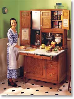
Tim Johnson Eighty years ago, before built-in cabinets were common, every modern homemaker wanted a “Hoosier” cabinet in her kitchen. As a baking center, it was the last word in efficient design and convenience, packed with labor-and time-saving features. Millions of Hoosiers, almost all manufactured by companies in Indiana, were sold before styles changed and built-in kitchen cabinets became the rage in the 1940s.
|
|
||
|
|
|||
|
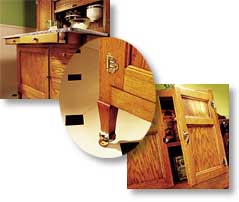
Why not put a Hoosier in your kitchen? Use it as a bread making center, a coffee bar, or to store dishes and linens or pots and pans. It’s still perfectly suited to today’s modern kitchens. This Hoosier is loaded with useful features. The center section slides in and out to maximize the usefulness of the porcelain enamel work surface. Two drawers are mounted under the work surface and slide with it, so their contents are always within reach. A tambour door provides access to the cabinet without the nuisance of swinging doors. |
|||
| Although it’s a big project with many pieces, this Hoosier cabinet is not hard to build. It’s made from dimensional 3/4-in.-thick wood. The cabinet joinery is simple, using dadoes, dowels and rabbets. The doors and cabinet sides are made with routed stiles and rails. The drawers are done on the tablesaw, and both the drawers and doors overlay the openings, so fitting them is a breeze. All the hardware surface mounts and you can buy the tambour ready to install! | |||
|
|
||||
|
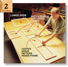
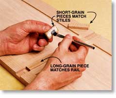
You’ll need a dado set for your tablesaw, a router, router table, and bits (stile and rail, round-over, and flush trim), a doweling jig and a drill. A jointer and planer are handy, but optional. For materials, you need 40 board feet of oak, one and one-half sheets of 3/4-in. A-1 grade oak plywood, two sheets of 1/4-in. A-1 grade oak fibercore plywood, and 15 board feet of 4/4 birch for drawer sides and runners—not bad for such a large piece. All the hardware, from the porcelain enamel top to the “ant traps” is available from companies that specialize in the restoration of antique Hoosiers (see Sources). Your cost will be about $475 for lumber and $300 for the tambour system and cabinet hardware. If you want to dress up the interior, as we did, with internal bins and canisters, you’ll spend another $200. Straight Grain Looks Best
Make the Doors and Cabinet Sides
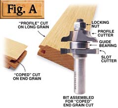
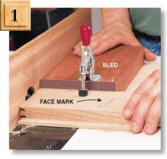
First Make these pieces into frames for the doors and sides using stile and rail cutters (see Sources) mounted in your router table. A reversible cutter set (Fig. A) won’t break your budget ($40 to $85) and making the change from one cut to the other only takes a few minutes. Make coped cuts (Photo 1), then rearrange the cutters for the profile cuts. Assemble the routed frames and find panels (C1 - C5). Finally, glue the parts together into doors (Z1, Z2 and Z5) and cabinet sides (D1 and L1). |
||||
|
|
|
|||||
|
|
|||||
|
|
|||||
|
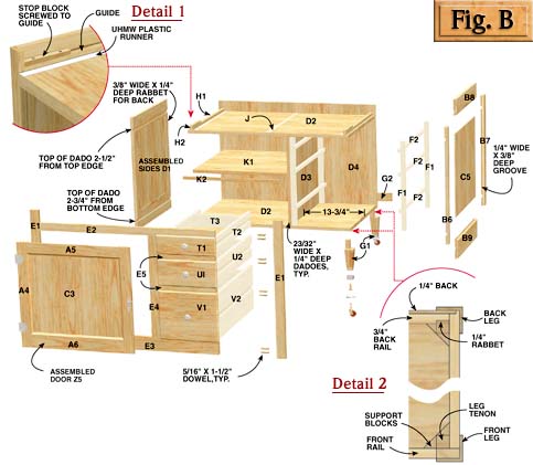
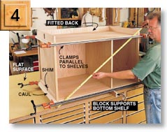
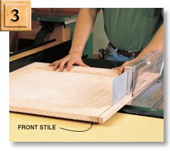
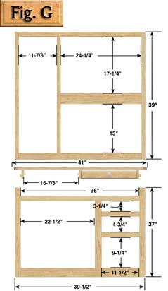
The upper and lower cabinets share joinery methods and have similar components. Make one and you’ll have no trouble with the other. Build the lower cabinet first (Fig. B). After making the sides (D1) and cutting them to width (Photo 3), square one end with a router and straightedge, then cut the other to finish length on the tablesaw. Make the top and bottom rails an extra 1/8-in. wide and the stiles an extra 1/4-in. long so you’ll have plenty of extra height to square the sides. After the sides are cut to size, cut rabbets in the back stiles for the plywood back. Cut the plywood shelves (D2) and divider D3). Then cut dadoes for them, after using scrap stock to set the depth and width. Fit the plywood back (D4) and then assemble the lower cabinet (Photo 4). |
|||||
|
|
|||||
|
|||||
|
|||||
|
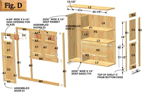
FIG. D EXPLODED VIEW OF UPPER CABINET
The upper cabinet is dadoed, like the bottom
cabinet, except for the flush-fitting top, which is rabbeted.
The tambour track hardware mounts to the walls behind the face
frame. Cabinet side brackets hold this cabinet above the lower
one leaving room for the center section in between. |
|||||
|
|
|||||
|
|
|||||
|
|
|||||
|
|

|
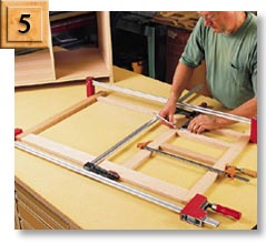
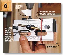
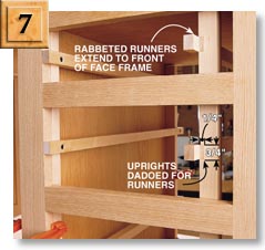
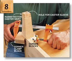
Finish the Lower Cabinet Install drawer runner assemblies in the lower cabinet. They fit behind the face frame so only the runners protrude into the drawer openings (Photo 7). Make the birch uprights (F1) first. They fit against the divider on the left and the cabinet side on the right. To locate the positions of the runners (F2), set one of the uprights in place behind the face frame and mark it for dadoes centered in each drawer opening. Use this piece to set up and cut the dadoes in all four pieces. Mill the runners from straight-grained birch stock so they’re flat and square. Cut rabbets in their front edges so they’ll extend beyond the uprights to the front of the face frame. Then screw them in place. The legs (G1) have long tenons for gluing behind the cabinet frame (Fig. B, detail 2). With the cabinet upside down, fit the tenons to the front inside corners of the cabinet, making sure the leg shoulders butt solidly against its bottom edges. Then glue them in place. Glue a rail (G2) to the back edge of the bottom shelf for the back legs, rabbeted so it fits between the leg tenon and cabinet back. After gluing, add corner blocks (Photo 8). Then drill holes in the legs and insert the caster sleeves. Turn the cabinet upright. Add guides (H1), stops (H2) and ultra-high molecular weight (UHMW) plastic strips (J) (see Sources) for the sliding center section in the cavity at the top of the cabinet (Fig. B, detail 1). Make sure the guides are perpendicular to the cabinet front and flush with the inside edge of the face frame stiles.
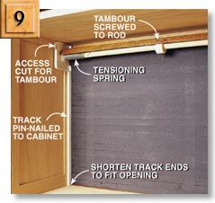
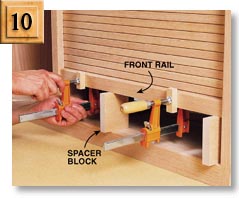
Adapting a dedicated tambour and track system made for a kitchen “appliance garage” (see Sources) saves the trouble of making a tambour and routing tracks for it in the cabinet. Instead, simply cut the plastic tracks (N1) to fit the opening and make an access slot in them for the tambour (N2) (Photo 9). Cut the tambour to width and then install the system following the manufacturer’s instructions. Make and attach the front rail (N3). Drill holes through the bottom slats of the tambour for fastening (Photo 10).
GLUE THE LEG to the lower cabinet. Then glue corner blocks to the leg tenon and cabinet frame. These mail-order legs (see Sources) are authentic Hoosier replicas, ready for skirts and casters.
THE TAMBOUR SYSTEM is a snap to install. The system works like a window shade, using spring tension to help lift and roll the tambour, which travels up and down in grooves in the plastic tracks.
CLAMP THE FRONT rail to the tambour and attach it from the backside with screws. The tambour and rail rest on spacer blocks that allow room for the clamps. |
|
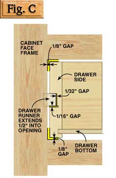
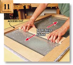
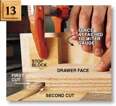
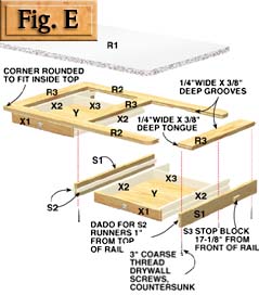
Cabinet side brackets (Q) (see Sources) hold the upper cabinet above the lower so the center section (Fig. E) has room to fit between them. The center section slides inside the cavity at the top of the lower cabinet, limited by stop blocks (H2 and S3) and the cabinet back. The porcelain enamel work surface (R1) fits neatly inside the concave curve of the side bracket. It contains a web frame for rigidity (Photo 11). Three rails (S1) support the center section and allow it to slide. The outer rails, spaced 1/32-in. narrower than the opening between the lower cabinet stiles, limit side-to-side travel. Dadoed runners (S2) in these rails hold narrow drawers (Fig. E). Cut dadoes in the rails and glue the runners in them before drilling holes for the mounting screws. Position the rails 11/4-in. back from the front edge of the porcelain enamel work surface to allow a sufficient overhang once the drawers are in place. Make the Drawers All the drawers (parts T, U, V and X) are side hung (Fig. C). Their joints are made using simple tablesaw cuts (Fig. F and Photo 13). The cabinet drawer fronts are lipped 3/8 in. on all four
sides so they overlay the openings. The cutlery drawer fronts have
lipped edges, but are flush top and bottom to maximize their depth.
Drill centered holes for the knobs before gluing the drawers together.
|
|||||
|
|
|||||
|
|
|||||


|
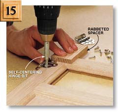
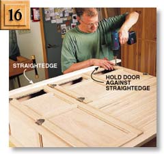
Rabbet the backsides of the openings at the top of the doors for the glass (see Sources). Then create the 3/8-in. lip on the door fronts by cutting a 3/8-in. square rabbet around their back edges (Photo 14). Test fit the offset hinges to make sure the lip is the right thickness. Put a door in its opening and lay a hinge on it. If the lip is too thick, the hinge won’t lay flat on the cabinet and the door will bind. First mount the hinges on the doors (Photo 15), then mount the doors on the cabinet (Photo 16). Apply Finish This Hoosier is finished with a medium-brown colored, oil-based gel stain topped with three coats of amber-toned waterborne poly. Before using them, I made double sure these two different finish products were compatible. First, both were made by the same manufacturer. Second, I read the labels, which verified compatibility by name. Gel stains are easy to apply and color surfaces evenly. I used two coats because I wanted a deep color. Toning the poly (see “Just Finishing” p. 106, December 1999 issue.) warms the color of the stained wood. Each coat enhances the effect. It’s an easy way to get a nice looking, durable finish. Before finishing, remove all of the hardware, sand everything and remove the sanding dust. Dampen the surfaces and sand again, lightly, because the waterborne finish will raise the grain, even through the oil stain. After letting the finish dry thoroughly, mount the glass (Z3) in the doors, reassemble your Hoosier, and (have your spouse) start baking!
|


|
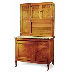
OVERALL DIMENSIONS 74" H X 42" W X 27" D |
|||||||||||||||||||||||||||||||||||||||||||||||||||||||||||||||||||||||||
|
|
|||||||||||||||||||||||||||||||||||||||||||||||||||||||||||||||||||||||||
Ref. - Qty. -
Dimensions - (Parts)
|
|||||||||||||||||||||||||||||||||||||||||||||||||||||||||||||||||||||||||
|
|
|||||||||||||||||||||||||||||||||||||||||||||||||||||||||||||||||||||||||
|
|
|||||||||||||||||||||||||||||||||||||||||||||||||||||||||||||||||||||||||

CUSTOMER SERVICE
INFORMATION
MY ACCOUNT
CONTACT US
-
ADDRESS:
Kennedy Hardware
10655 Andrade Drive, Zionsville
46077, Indiana
United States -
TELEPHONE:
317-873-1316 -
EMAIL
Contact Us


Copyright © 1983-2024 Kennedy Hardware